Published on: May 21, 2021
Welcome to our latest blog. In this blog, we will discuss channel modeling in the mmWave frequency band. First, we will explain why channel modeling in mmWave is essential, and afterwards, we will describe how to use a Ray Tracer (RT) to model the channel. In the context of channel modeling simulations, we will introduce the Q-D channel realization tool as an example of an open-source RT tool and describe an example scenario in an L-shaped room generated with this tool. Finally, we will conclude the blog by explaining the demands of accurate channel modeling on higher frequencies, in particular THz.
Introduction
In 5G cellular systems, larger bandwidths in the order of GHz can be used to fulfill the demand for high data rates. Due to the overutilization of the sub-6 GHz spectrum, higher frequency bands such as mmWave, have attracted researchers’ attention in the past decade. Despite the advantages of higher bandwidth, propagation at MmWave raises two critical challenges: severe path loss and high sensitivity to blockage. This phenomenon makes the mmWave channel highly unreliable to mobile users [1]. Deploying wireless systems requires an accurate understanding of the channel propagation characteristics to fulfill the need for reliable communication. One way to achieve this is by using experimental testbeds to measure and model the channel performance in the real-world with high accuracy. However, high cost and limited flexibility make this option difficult for most researchers. Therefore, theoretical analysis and computer-aided simulations can be very valuable tools for channel modeling at mmWave frequencies. RTs are based on the principal concept of computer-aided simulation to model channel propagation. They can be used to simulate and model channel propagation in specifically defined scenarios. RTs trace a path by computing the image of the transmitter and receiver based on the geometry plane and location of devices to identify the valid paths. RTs rely on the geometry and characterize the different features of each ray, including Time of Arrival, Angle of Arrival, Angle of Departure, Path Loss, time Delay, etc. [2].
Introducing the Q-D Channel realization tool [3]
In this section, we introduce Q-D Channel Realization as an example of the RT tools. The Q-D Channel Realization software is an open-source 3D RT tool in MATLAB developed by the National Institute of Standards and Technology (NIST) in collaboration with the University of Padova [4]. This tool provides a flexible and scalable channel model for mmWave frequencies. Some of the remarkable features of this tool include:
- Multiple-Input Multiple-Output (MIMO) support
- Mobility support
- Configurable antenna orientation
- Configurable device orientation for each device
- Output compatible with the widely used network simulator ns-3 (an example of ns-3 integration implementation can be found in [5]).
This software supports two types of propagation measurements. The first one is based on the NIST statistical distribution, and the second one is based on channel model documents 802.11ay Task Group (TGay). Using TGay measurements allows user-defined libraries to model channels, which is valuable for modelling channels at higher frequencies.
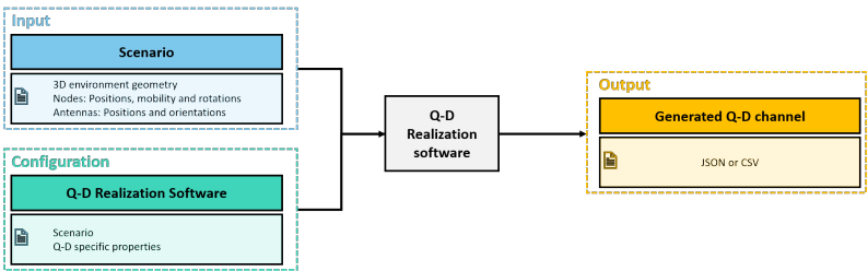
Figure 1: The Q-D Channel Realization software workflow [4]
Figure 1 describes the workflow of the Q-D channel realization tool. The first step in defining the scenario includes environment geometry and material, node topology and mobility, and antenna positions and rotations. The second step is configuring the propagation parameters such as reflection order, measurement type, and diffuse component properties. With this information, the Q-D channel realization tool generates a channel model that for each ray defines the output channel parameters, including the angle of arrival, angle of departure, path loss, order of reflection, etc.
L-room Channel Modeling Example
This example illustrates how the use of RT tools can help understanding and analysis of channel propagation in specific NLOS scenarios, such as an L-shaped room seen in Figure 2. We chose this scenario since it covers both channel conditions – the LOS and NLOS. As illustrated in Figure 2, in the beginning, the channel between the transmitter and the receiver is Line of Sight (LOS). After some time, as the receiver moves across the room, the direct link between the two devices gets interrupted, and the channel condition changes to NLOS. In this condition, there is still a connection using the first and second order reflections. Eventually, however, the communication link relies just on the second order reflection. A considerable path loss in the second order reflection ray can affect the reliability of the communication link. One solution to enhance reliability in such a situation is by using a Reconfigurable Intelligent Surface (RIS). If you’re interested in how these arrays work, you can read more about them in our previously published blog on RIS.
Figure 2: Visualizing propagation channel modeling for L-Room example.
Future of channel modeling and conclusion
Following recent advances in THz technology, it is likely that future 6G networks will utilize communication in the THz range to achieve a higher data rate. Due to the even higher frequency range, THz communication will use more directional antennas leading to high path loss and attenuation due to blockage, and channel modeling will play a critical role in increasing reliability. Right now, most RTs only support mmWave frequencies (up to 100 GHz) and despite the introduction of RTs that support channel modeling in the THz range [6], more profound studies in order to accurately model channels in this frequency range will be required.
If you were able to stick until the end and can’t wait for more content and you also want to know about us and our projects, you can always follow our social media channels.
References
[1] F. Erden et al. “28 GHz mmWave channel measurements and modeling in a library environment”, In 2020 IEEE Radio and Wireless Symposium (RWS), 2020, pp. 52-55.
[2] M. Lecci et al. “ Accuracy vs. Complexity for mmWave Ray-Tracing: A Full Stack Perspective,” arXiv preprint arXiv:2007.07125. 2020 Jul 14.
[3] M. Lecci et al. “Quasi-Deterministic Channel Model for mmWaves: Mathematical Formalization and Validation,” arXiv preprint arXiv:2006.01235. 2020 Jun 1.
[4] https://github.com/wigig-tools/qd-realization
[5] https://github.com/signetlabdei/qd-channel
[6] S. Tarboush et al.“ TeraMIMO: A Channel Simulator for Wideband Ultra-Massive MIMO Terahertz Communications,” arXiv preprint arXiv:2104.11054. 2021 Apr 22.