Published on: May 28, 2021
In modern wireless communications, beamforming is a widely used technique to reduce the interference between multiple links and increase the signal-to-noise ratio. This technique can be interpreted as “pointing” the signal towards a specific device, but this definition is not always obvious and does not explain how it is done. To better understand this concept, in this blog, we present a tutorial on how to realize a simple audio beamforming system, with the use of nothing but a laptop and listen to the effect it produces.
The experiment
Like radio waves, sound waves can be beamformed too. What you will need for this experiment is a set of stereo speakers (e.g., those embedded in most laptops) and an open-source audio editing software called Audacity, which can be downloaded from [1].
First of all, you need to measure the distance between the speakers (if the speakers are embedded inside a laptop, you can use the width of the laptop as an estimate). This will be the wavelength, of the sound that you need to use for the experiment. To find the corresponding frequency, you need to divide the speed of sound in air ν = 343 m/s by the wavelength(λ in meters), applying the formula f=ν/λ. For example, if the distance between the speakers is 0.34m, you would have f = 343/0.34 = 1000Hz.
Now that you know the frequency to be used, you can open Audacity and perform the following tasks, also shown in Figure 1.
- Create 2 stereo tracks
- Select the first 30s of the first track
- Open the nyquist prompt of the software
- Type in the command (mult (hzosc f) (hzosc 1)), replacing f with the frequency you calculated
- Repeat steps 2-4 for channel 2, using the command (mult (hzosc f) (hzosc 2))
- Choose only one of the stereo tracks and split it into two mono tracks
- Zoom in until you see the waveform
- Move one of the two mono tracks of half a wave, so that the maximum of one channel matches the minimum of the other
You are now ready to listen to the audio signal. You can press the “play” button on the software and move your head around the speakers. You should be able to perceive that the sound you hear when you are in front of the speaker is different from what you hear when you are slightly to the side. This is because one track is beamformed (i.e., “pointed”) towards the front of the speakers, whereas the other track (the one that has been split and shifted) is beamformed towards the side.
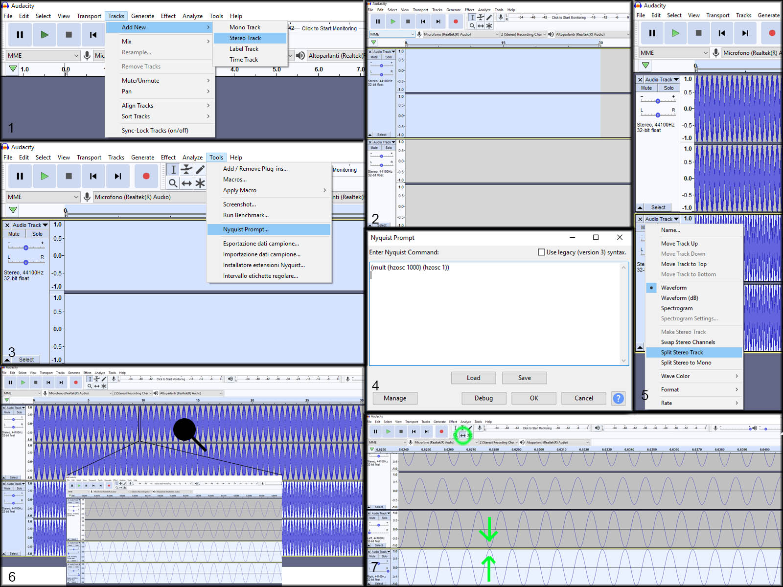
Figure 1: Steps to create beamformed audio
The operating principle
Now that you have listened to beamforming, we try to understand how this works. In Figure 2, you can see that when you are directly in front of the speakers, the waves that have not been shifted, represented in red, arrive at your ear together (technically, we say that they arrive in phase) because they are equally far from you. The waves that have been shifted (in step 7), instead, arrive with a delay of half a period (out of phase). When the two in-phase waves combine, we have constructive interference, and therefore, they sound louder, whereas with the out-of-phase signal we have destructive interference, so the two waves cancel each other. In contrast, when your ear is slightly to the side, the signal from the speaker that is further away from you has to travel a longer distance. Hence, the waves that start in-phase arrive out of phase and thus cancel each other out and the waves that start out of phase arrive in phase and are therefore perceived louder. For this reason, we can say that the sound from the track that has not been shifted is “pointed” to the front of the speaker, whereas the sound from the track that has been shifted is pointed slightly to the side.
It should be noted that this sum and cancellation of the signals is not perfect. You will have some other waves that reflect from the wall and recombine with the original signal. For this reason, based on the acoustics of the room you are in, you might only barely hear the difference. This also happens with radio waves and is one of the reasons why applying this technique is not trivial.
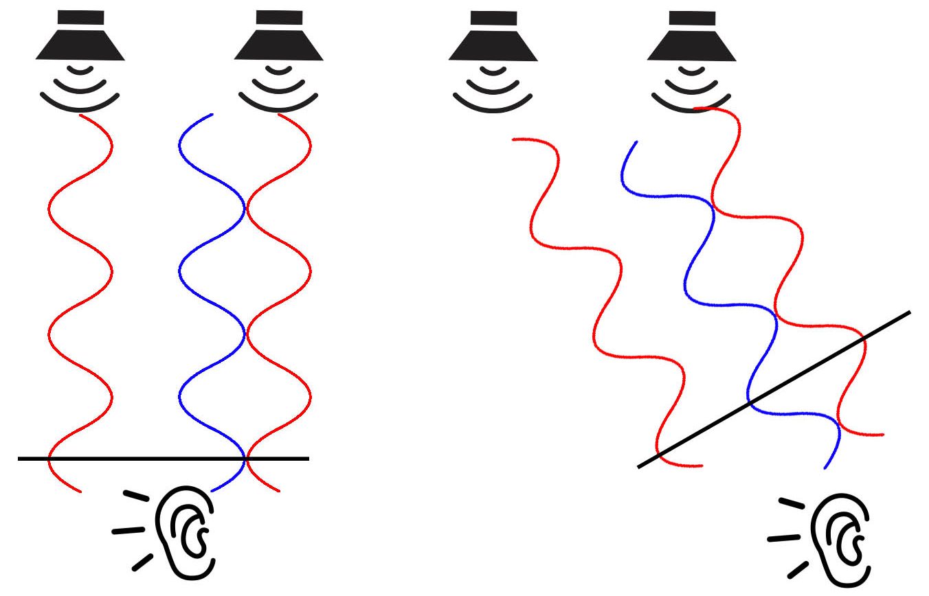
Figure 2: Operating principle
Conclusion
With this experiment, you have first hand experience and a basic understanding of how it is possible to “point” a signal in a certain direction. Starting from this very basic idea, mmWave transmitters can transmit different signals in different areas, and therefore, serve multiple devices at once (also known as spatial multiplexing). It is also possible to use this technique to increase the received power at a receiver, overcoming the high loss experienced by mmWave signals. Of course, this experiment is not enough to deeply explain all the details of beamforming and the current technology on the topic is very advanced and complicated. But nevertheless, we hope that this tutorial helped you to understand and experience the basic principles in a practical and interesting way.
If you were able to stick until the end and can’t wait for more content and you also want to know about us and our projects, you can always follow our social media channels.
References
[1] https://www.audacityteam.org/