Published on: Apr 6, 2022
The EM waves that are being thoroughly exploited for next-generation high-speed telecommunications, include mmWaves, Terahertz, and light. They are all oscillations in the electromagnetic field, and as such, they share a lot of common properties. In particular, in this article, we will focus on one of the most well known properties we see in light: refraction. This is a property that we see in our daily life when we use lenses, for example in our eyeglasses or cameras. It is the effect due to which light bends when it travels through different materials. Despite the huge difference in wavelength between visible light waves and the radio waves we use in communications, refraction also happens in the latter case. In this article, we will discuss how it is possible to use it to our advantage.
Designing a mmWave lens
One question that might arise from the statements in the introduction is “Can we use lenses to focus radio waves as we do with light, and improve the radio communication links?” The answer is Yes. Thanks to our knowledge of the physics of EM waves, we absolutely can.
So, without further ado, let’s design a lens for mmWaves!
First of all, we need to find a suitable material to build it. The first material that might come to mind is glass, as this is what most lenses for visible light are made of. At the mmWave frequencies, however, this is not a great choice. Radio waves and visible light have very different wavelengths (hundreds of nanometers for light, and tens of millimeters for mmWave) and the material properties vary with wavelength. While glass is known to let the light through, it can block a good portion of the energy at the mmWave frequencies. Conversely, the vast majority of plastics are opaque to visible light, but they do let radio waves through and bend them similarly to what glass does for visible light. The amount by which the field is bent is determined by its relative dielectric constant, ranging from 1 (no effects) to around 4 for plastics. Higher dielectric constants can be obtained in materials such as ceramic, but they are typically more expensive, more difficult to manufacture, and less robust. For these reasons, plastic is typically the best choice.
Now that we have found the right material, we need to figure out what size the lens has to be. This value depends on the operating frequency of the communication device. In this article, we assume that the transmission happens at 60 GHz. At this frequency, the wavelength of an electromagnetic wave is 5mm. The lens needs to be significantly larger than the operating wavelength to function properly, therefore, we know that the size of the lens must be around 1 cm to a few centimeters at least.
The choice of the shape is a more involved process, and there is not a unique right answer, but a few common simple shapes are spheres, sections of spheres, and half-cylinders.
So we finally have all the puzzle pieces and can propose a structure for our lens: For the material, we use high density polyethylene or HDPE. This is a kind of plastic with a dielectric constant of around 2.5, that causes significant but not excessive refraction. This material is also very commonly used for all sorts of applications, so it is widely available. We choose to use a half-cylinder shape, as this shape is easy to manufacture, for example by continuous extrusion. As for the size, we want to make our lens as small as possible to limit the dimension of the final device, so we choose a diameter of 1.5cm and a length of 3cm. It should be noted that to achieve good performance, the exact values need to be optimized with numerical simulations. This process is very complex and outside of the scope of this article, but we hope that the reader will still get a good understanding of the rationale behind these choices.
From the same numerical simulations we used in the design process, we can also characterize the lens. Thanks to modern electromagnetic simulation software, we can compute how the field propagates through it. In Figure 1, it is possible to see how the field generated by a 60 GHz patch antenna propagates through space without the lens, whereas Figure 2 shows how the same field bends with the lens.
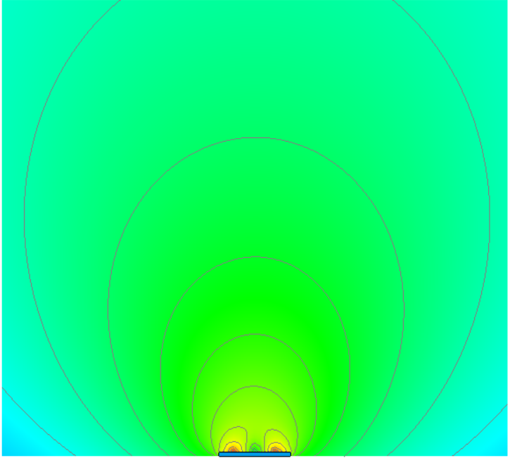 Figure 1: Field propagating from a 60 GHz patch antenna
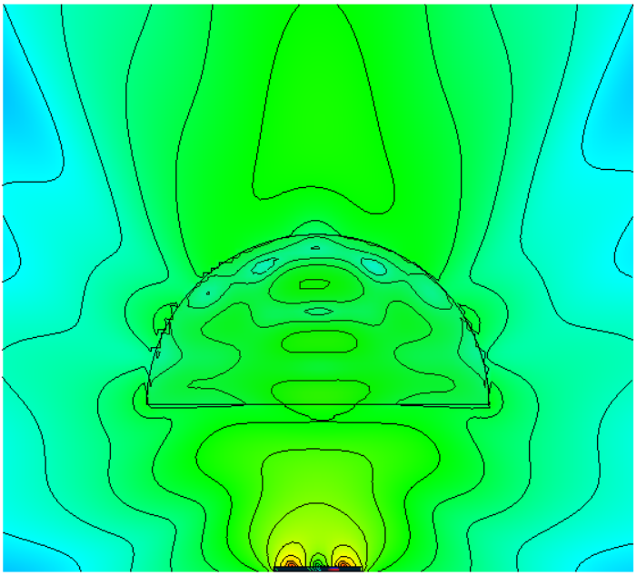 Figure 2: Field propagating from a 60 GHz patch antenna through a lens
It is clear that we succeeded in bending the energy towards the front of the transmitter, but how much will this improve the communication? It is possible to calculate that, for an antenna placed in front of the transmitter, the received power will increase by almost 10dB (i.e., the received power with the lens is 10 times as much as the one without). In terms of range, in an open area without obstacles, this would increase the operating distance by roughly 3 times. It should also be noted that greater gains and more focused beams can be obtained with bigger lenses and materials with a higher dielectric constant.
Applications
As we have seen, dielectric lenses can effectively focus the energy of a transmitter in one specific direction, and can be made very easily out of cheap materials like plastic. So why are they not used everywhere?
The main drawback of lenses is that the direction where the energy is concentrated is fixed, and cannot be changed without a mechanical action. In contrast, array-based beamformers can steer the beam extremely quickly and direct the energy in different directions without any mechanical change to the structure.
For this reason, the use of dielectric lenses is limited to those applications where the beam direction does not change, such as fixed point-to-point links and some kind of radars.
For all the applications where the beam needs to be redirected, such as cellular base stations, lenses cannot be used effectively. Moreover, as stated before, lenses cannot be extremely small. This makes their use in some applications (e.g., smartphones) infeasible due to constraints on the dimension of the final device.
Conclusion
Dielectric lenses are a cheap and easy way to increase the directivity of an antenna. Although they are not a replacement for array-based beamforming, they are a great alternative for some specific applications. In those applications, their use could significantly reduce the cost, power consumption, and environmental impact of the device they are used in, as they do not require complex electronics to operate.
Regardless of their use, they are an interesting and counterintuitive piece of technology. They challenge the misconception that an antenna is just a metallic structure, and show that a mere piece of plastic can improve its performance by one order of magnitude or even more.
This might look like magic. Rest assured it is not, it is science instead!
If you were able to stick until the end and can’t wait for more content and you also want to know about us and our projects, you can always follow our social media channels.