Published on: Jul 30, 2021
Where to point the beam? – Local Area Networks (LAN)
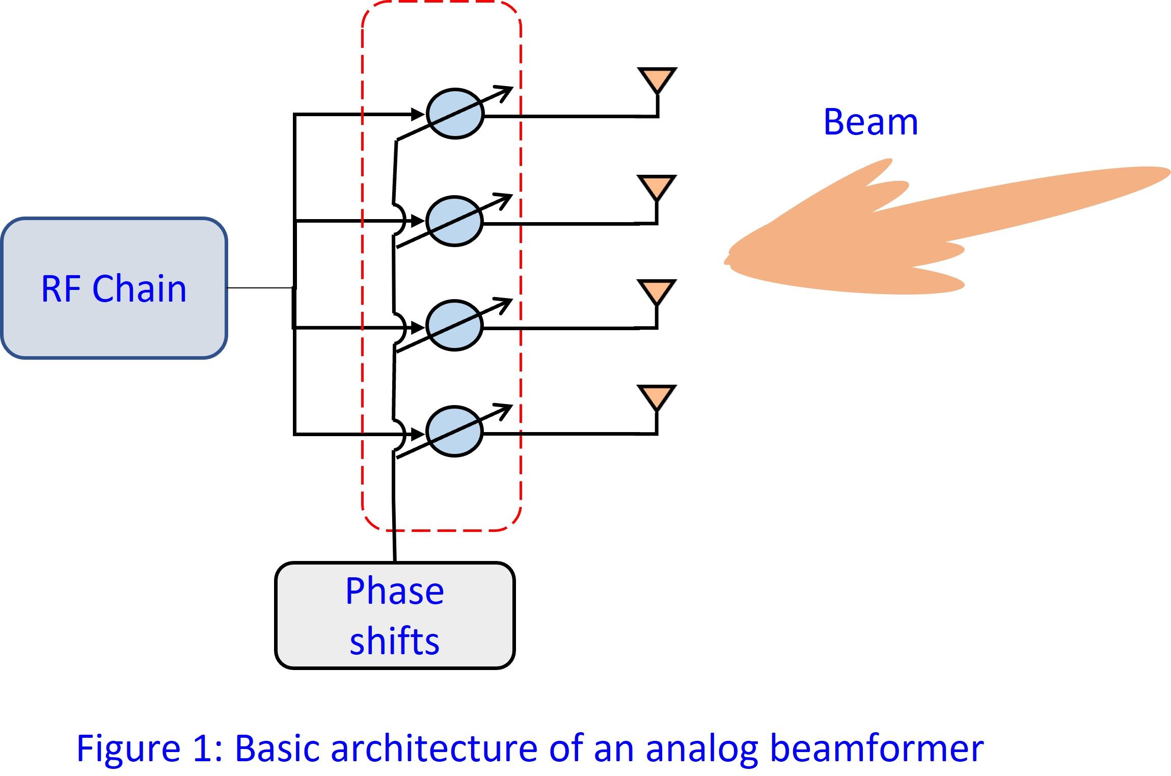
The earliest beamforming technique (Bartlett beamformer) dates back to World War II. Although beamforming techniques have advanced a lot since then, they have not been deployed in communication systems until recently. Beamforming is simply radiating or capturing energy from a specific direction using an array of antennas. The basic architecture of an analog beamformer equipped with a phased antenna array is depicted in Figure 1.
An analog beamformer works as follows: The bandpass signal from the radio frequency (RF) chain is fed to elements of the antenna array by inducing a phase change. When the antennas radiate the signal, due to constructive and destructive interference of the phase-shifted signal, a beam is formed in a particular direction. To get an intuitive feel of beamforming, you can read one of our previous blogs: “Have you ever heard (of) Beamforming?”. Also, note that there are other architectures of beamforming, such as digital beamforming or hybrid analog-digital beamforming, but this blog will only cover analog antenna beamforming. Hopefully, the above explanation and our previous blog have allowed you to understand how a beamformer works, but the question “Where to point the beam?” still remains unanswered. To get this answer, let us start with the objectives of a beamformer.
The three main objectives of a beamformer are:
- To direct the maximum transmit signal power in the direction of the receiver, also termed transmit beamforming. Similarly, the receiver collects the signal from a particular direction that maximizes the received signal power, often termed as receive beamforming.
- To estimate the direction of the receiver. From the receiver perspective, this is done by estimating the direction of arrival (DoA) of the plane waves impinging on the array.
- To support user mobility by either tracking the direction or by estimating the direction quickly.
These three operations jointly help set up and maintain the directional links throughout the communication process, known as beam management. The second objective is what is termed as beamforming training. To describe in a nutshell, Beamforming training is the process of determining the optimal antenna phase shifts that maximize the radiated or captured energy in a certain direction. In the remainder of this blog, we will explain how beamforming training is done in LAN systems.
Beamforming @ Sub-6 GHz systems
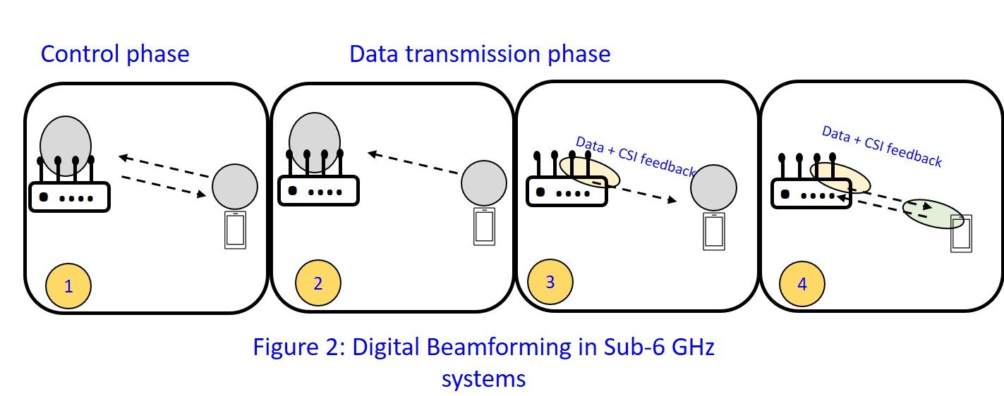
An ideal isotropic antenna at the transmitter radiates equally in all directions. A receiver in the vicinity receives a fraction of radiated power which is directly proportional to the transmitted power, antenna gains and inversely proportional to the distance [1]. In legacy WiFi and current LTE systems, this fractional power is sufficient enough to establish a communication link. To this end, it is safe to say that existing systems have no need for beamforming. Nevertheless, multiple antennas at the transmitter and/or receiver can be used to enable beamforming, in order to enhance the signal-to-noise ratio (SNR) and also reduce the interference to the other users. Now, the question is how are the necessary phase shifts acquired? In general, communication can be split into two phases; control phase during which the communication link is set up, followed by the data transmission phase. Current LTE and WiFi systems use omnidirectional transmissions in the control phase. During the data transmission phase, the receiver applies digital/analog beamforming based on the estimated channel state information (CSI). Later, raw/quantized CSI is informed to the transmitter via feedback which is used to perform beamforming at the transmitter. So, in current LTE and legacy systems there is no need for explicit beamforming training. The complete process of beamforming is pictorially depicted in Figure 2.
Beamforming training @ mmWave systems
Unlike legacy and current LTE systems, directional communication is essential for mmWave systems. As mentioned in our “mmWave vs Sub-6 GHz” blog, the main reasons for this are severe path loss, human blockage and atmospheric absorption. A communication link cannot be established using omnidirectional signalling as in sub-6 GHz systems since the link budget is too low. This motivates the need for beamforming and explicit beamforming training even to establish a link (Initial Access). Moreover, mmWave systems allow multiple antennas to be fit in a small form factor due to their high operational frequency, thus providing a way to improve the link budget. Several methods have been proposed for efficient beamforming training, which can be broadly classified into two types: hierarchical beam training and exhaustive search beam training. Another class of beam training methods is the hybrid beam training approach which combines the merits of hierarchical and exhaustive beam training methods.
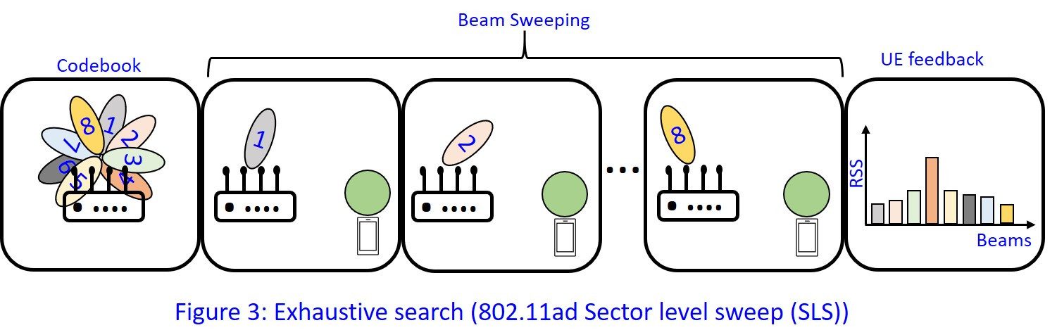
Exhaustive search beam training [3]: This approach is adopted in IEEE 802.11ad systems and depicted in Figure 3. The access point (AP) in need of an appropriate beam pattern starts to sequentially transmit control packets using narrow beams from a predefined codebook. The receiver node (i.e., user equipment, UE) uses a quasi-omnidirectional pattern and evaluates the quality of the received signal using received signal strength (RSS) or SNR. Later, the UE repeats the same process but includes the identifier of the best beam pattern in every control packet. Finally, the AP replies with the best beam pattern identifier to the UE. This process is also called sector level sweep (SLS). While the goal of the SLS is to establish a link, the beam refinement protocol (BRP) helps to optimize the beam selection as the communication goes along and strongly relies on SLS training. Unlike SLS, which needs one packet each for a sector, BRP allows training multiple sectors within a single packet. BRP helps to overcome the effects of mobility and blockage by continuously adapting the beam patterns.
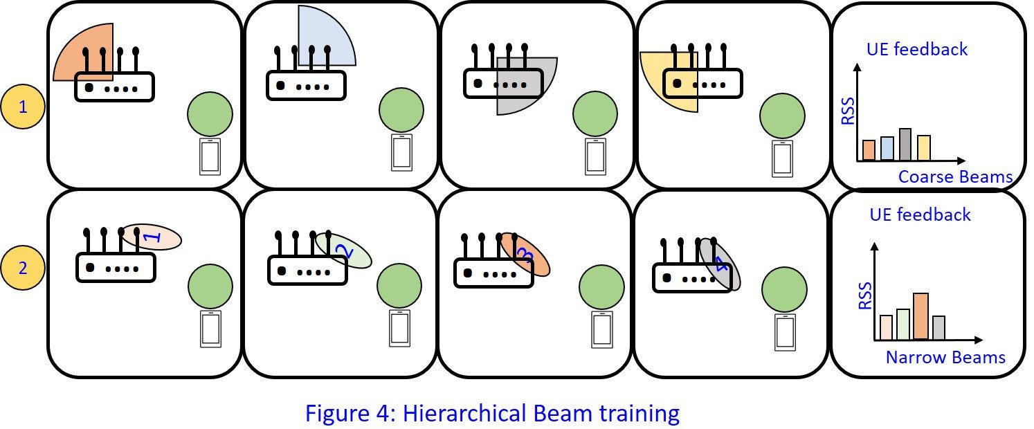
Hierarchical beam training [4]: In this approach, the AP iteratively refines the beam pattern based on UE feedback (see Figure 4). The AP starts with wide beams and once it receives the optimal sector from the UE, it refines the sector by training narrower beams. The UE repeats the same process to obtain the optimized phase shifts.
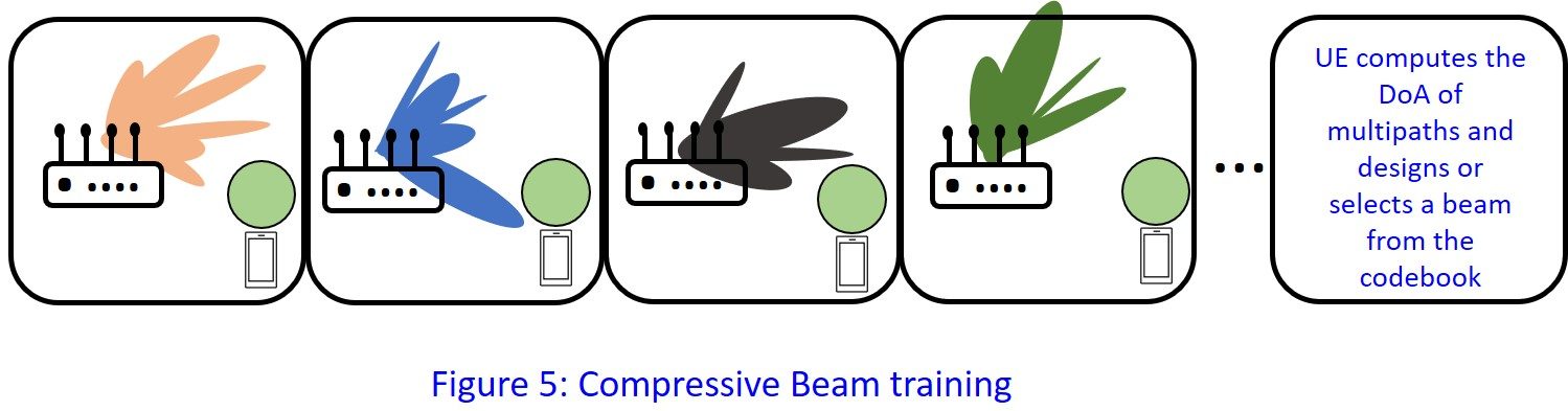
In the exhaustive search approach, overhead increases linearly with the size of the codebook. At first glance, the hierarchical method may seem to have less overhead but as the number of users increases, overhead increases drastically. One approach which aims to reduce the overhead is the compressive beam training framework proposed in [2]. In this approach, the AP uses M random beam patterns from the codebook of size N (M<N). The UE estimates the DoAs of the dominant path taken by the signal using compressed sensing technique. Finally, the UE maps the estimated angle of arrival to the best beam pattern from the codebook. Thus, with only M frames the UE completes its beam training. Similarly, the process is repeated for the AP beam training. The compressive sector selection technique which combines the best features of exhaustive and hierarchical search methods is depicted in Figure 5.
Despite the simplicity of the addressed beam training mechanisms, they are suboptimal and mostly applicable for static environments. Furthermore, none of the approaches can adapt the beams based on the operating environment. The single RF chain limits the exploitation of the rich scattering environment to establish multiple data streams. For this reason, the IEEE 802.11ay standard [5] introduced multiple RF chains but that further complicates the beam training procedure. While the ingredients (SLS, BRP) of beamforming training in IEEE 802.11ay have similar roles, SLS must be performed for each RF chain separately. To conclude, there is a significant need for the development of quick beam training procedures with reduced overhead. This is the story of beam training in LAN networks. The beamforming training of outdoor 5G networks is completely a different ball game and that will be the story of another blog!
If you were able to stick until the end and can’t wait for more content and you also want to know about us and our projects, you can always follow our social media channels.
Citations
[1] https://en.wikipedia.org/wiki/Friis_transmission_equation
[2] D. Steinmetzer, D. Wegemer, M. Schulz, J. Widmer, and M. Hollick, “Compressive millimeter-wave sector selection in off-the-shelf IEEE 802.11ad devices,” in Proc. ACM CoNEXT, Nov. 2017, pp. 414–425.
[3] T. Nitsche, C. Cordeiro, A. B. Flores, E. W. Knightly, E. Perahia and J. C. Widmer, “IEEE 802.11ad: directional 60 GHz communication for multi-Gigabit-per-second Wi-Fi [Invited Paper],” in IEEE Communications Magazine, vol. 52, no. 12, pp. 132-141, December 2014.
[4] Z. Xiao, T. He, P. Xia and X. Xia, “Hierarchical Codebook Design for Beamforming Training in Millimeter-Wave Communication,” in IEEE Transactions on Wireless Communications, vol. 15, no. 5, pp. 3380-3392, May 2016, doi: 10.1109/TWC.2016.2520930.
[5] C. R. C. M. Da Silva, J. Kosloff, C. Chen, A. Lomayev and C. Cordeiro, “Beamforming Training for IEEE 802.11 ay Millimeter Wave Systems,” 2018 Information Theory and Applications Workshop (ITA), 2018, pp. 1-9, doi: 10.1109/ITA.2018.8503112.