Published on: Feb 4, 2021
Massive Multiple-Input Multiple-Output (MIMO) at mmWave is a breakthrough technology for the next generation of communication. Massive MIMO uses a large number of antenna elements to focus the energy towards the receiving antenna, while the mmWave band provides more bandwidth for communication. The main challenge in shifting towards mmWave is the path loss that occurs at higher frequencies. To overcome this issue, directive antennas are used along with beamforming. The principle of beamforming was presented in the blog, have you ever heard of beamforming? [1] and analog beamforming and beam training methods were presented in the blog where to point the beam? [2]. The present blog “Beamforming architecture in Beyond-5G mmWave Networks” focuses on the different beamforming architectures that relate to the hardware architecture of a communication setup, namely, Digital beamforming, Analog Beamforming, and Hybrid beamforming architectures. Selecting the appropriate hardware architecture results in low price and low power consumption for communication systems. The goal of beamforming architectures is to reduce the complexity of the hardware while keeping the system performance high.
Beamforming architectures
Conventionally, massive MIMO is a system in which the base station has many antennas serving multiple single-antenna users. Typically, the number of base station antennas is one order of magnitude more than the number of users. Since we have a large number of antennas at the base station, we can generate and allocate separate narrow beams to each user. This beam allocation is called spatial filtering. So, each user can use the same time and frequency resources simultaneously, but illuminated with separate antenna beams. By applying appropriate phase shifts to each element of the antenna array, the pattern of the antenna is steered in the desired direction, which is called beamforming. The main goal of beamforming is to create a directional path between the base station and the user through separate array beams. These spatial beam diversities increase the spectral efficiency, energy efficiency, and security of the link. In an analog beamformer, the received signals are combined coherently at RF while in digital beamformer, the coherent combination of the received signal from each element occurs after digitizing the RF signals. The beamformer architecture is a hot research topic aiming to reduce the number of RF chains by optimizing and combining the analog and digital beamformers.
In the Digital Beamformer (DBF) architecture, each antenna element is connected to a Radio Frequency (RF) chain. In other words, the number of RF chain and antenna elements is equal, as shown in Figure 1(a). Each RF chain consists of Analog to Digital Converter (A/D), Digital to Analog (D/A), upconverter, amplifiers, filters, and switches. In the digital beamforming process, all the beamforming algorithms and phase shifts are implemented in baseband after digital sampling. This architecture benefits from flexibility in pattern and high performance, where multiple beams can be generated simultaneously; however, it is costly and power-consuming. Furthermore, calculating the channel state information for digital beamformers at massive MIMO suffers from overhead.
In the Analog Beamformer (ABF) architecture, one RF chain is connected to all antenna elements by an analog beamformer network, as seen in Figure 1(b). In this architecture, the antenna phase shifts are controlled with external hardware called phase shifters.

Figure 1. Beamforming architectures: (a) Digital beamformer; (b) Analog beamformer; (c) Hybrid beamformer [3].
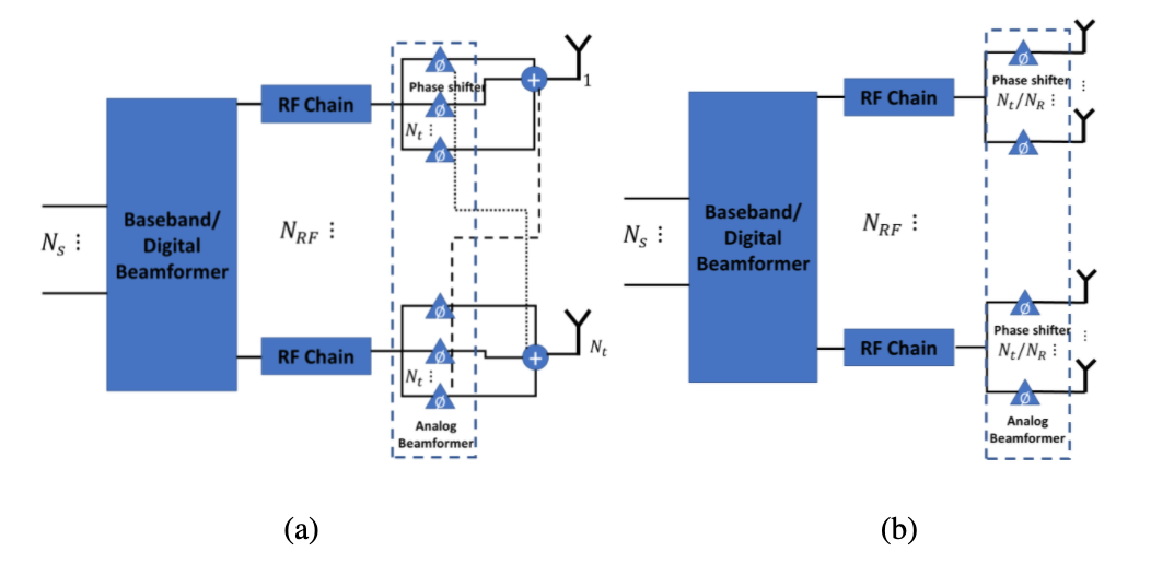
Hybrid Beamformer (HBF) phased array technology exploits the low cost and energy efficiency of mixed-signal RF components to implement cost-effective MIMO transceivers. This approach has received significant interest in exploring new architectures for the RF chain. The most common kinds of hybrid beamformers are i) fully-connected and ii) partially-connected HBF. In the former, all the array elements are connected to an RF chain, as shown in Figure 2(a). In contrast, in the latter, each sub-array of antennas is connected to an RF chain as shown in Figure 2(b). The partially connected structure benefits from the reduced cost and complexity compared to the fully connected architecture.

Figure 2. Hybrid Beamformer architectures: (a) Fully-connected Hybrid beamformer; (b) Partially-connected Hybrid beamformer [3].
To reduce the processing in hybrid beamforming architecture, the analog beamformer is usually implemented by Discrete Fourier Transform (DFT) vectors selected from a predefined codebook or lens beamformers. The analog DFT beamformers are implemented by Buttler matrices, Rotman lenses, etc. [4]. These DFT beamformers benefit from low complexity and low cost.
If you were able to stick until the end and can’t wait for more content and you also want to know about us and our projects, you can always follow our social media channels.
Citations:
[1] Bedin, Andrea. 2021. “Have you ever heard (of) Beamforming?” https://b5g-mints.eu/blog9/
[2] Sai Pavan Deram. 2021. “Where to point the beam? – Local Area Networks (LAN)” https://b5g-mints.eu/blog14/
[3] Ahmed, Irfan, et al. “A survey on hybrid beamforming techniques in 5G: Architecture and system model perspectives.” IEEE Communications Surveys & Tutorials 20.4 (2018): 3060-3097.
[4]. Skolnik, Merrill I. “Introduction to radar.” Radar handbook 2 (1962): 21.


